I have been interested in the topic of emulation for many years; in particular, game console emulation. I started playing games under emulators when I was a teenager and I was fascinated by how a piece of software would let me play a game in a completely different architecture than the original one.
I’ve you’ve ever been interested in learning about emulation, maybe you’ve learned about the CHIP-8; a specification of a simple virtual machine designed to play 8bit 2D videogames in the mid 1970s. The connection between the CHIP-8 and emulation development is that the specification of the CHIP-8 is very simple and makes the perfect target for writing your first emulator. In fact, that’s what I did in 2014: I wrote my first emulator, targeting the CHIP-8 in C++. Please, don’t take that C++ code too seriously! I’ve never been experienced in C++, and I wasn’t very experienced in software development by then.
A year ago a friend of mine was interested in both practicing bit and bytes manipulation and programming in Rust. I believe I suggested him to write a CHIP-8 emulator, and I decided to join the fun as well, and write my second CHIP-8 emulator in Rust, as a weekend project.
In this article I will explain some basic concepts of the CHIP-8 and how to
design an emulator for it in Rust, following patterns common to simple
emulators. The emulator will run under a PC desktop OS (I use Linux with
x86_64) using the SDL libraries. In a future article I will explain how to
port the emulator to a baremetal ARM embedded microcontroller.
You can find the source code of the emulator in github
CHIP-8
The CHIP-8 is a specification for a simple virtual machine for 2D games. It’s virtual because there was not a hardware implementation, and it was designed so that implementations of the virtual machine (emulators) could be written for different machines allowing the same games to be played in different environments. Since it was designed in the 1970s, the specs of the VM are very low compared to current standards.
Here are some features of the CHIP-8
- Monochrome 64x32 pixels display
- 4KB of Memory
- 512B reserved
- 3.5KB of RAM shared with the game program
- 16 x 8 bit registers
- 16 key keypad input
- delay timer
- sound timer
- 36 instructions
If you’re interested in building an emulator for the CHIP-8 I recommend you to read Cowgod’s Chip-8 Technical Reference v1.0
Emulator architecture
The emulator will be split into two parts: frontend and backend. The backend is developed as a Rust library; and the fronted imports the backend library to build an executable. The reasoning behind this division is to keep the backend completely isolated from the input and output so that it has maximum portability, and leave the implementation details of input and output at the frontend. This way if we want to port the emulator to a new system we only need to take care of making a new frontend and we can reuse the backend.
To implement this division I made use of Rust
workspaces. The
root of the repository contains a
Cargo.toml with
the following contents:
[workspace]

members = [
    "chip8",
    "sdl",
]
Where chip8 is the Rust project corresponding to the backend, and sdl is
the Rust project corresponding to the desktop frontend.
Backend
The backend is implemented in the chip8
folder and contains the
core implementation of the CHIP-8 Virtual Machine.
Structure of the emulator
The CHIP-8 emulator is implemented via a struct:
pub struct Chip8<R: RngCore> {
    mem: [u8; MEM_SIZE],
    v: Regs, // Register Set
    i: u16,  // Index Register
    pc: u16, // Program Counter
    stack: [u16; 0x10],
    sp: u8,                                     // Stack Pointer
    dt: u8,                                     // Delay Timer
    st: u8,                                     // Sound Timer
    keypad: u16,                                // Keypad
    fb: [u8; SCREEN_WIDTH * SCREEN_HEIGTH / 8], // Framebuffer
    tone: bool,                                 // Tone output enable
    time: isize,                                // Overtime in microseconds
    rng: R,                                     // Instance of a random number generator
}
which contains an abstraction of all the hardware components of the CHIP-8 as
well as some auxiliary fields. A part from the CPU and memory, the CHIP-8
contains very simple hardware, so I implemented all the required methods on the
Chip8 struct. For more complex hardware (like programmable timers, or a more
complex display), I would have created abstractions via new structs (which
would appear in the Chip8 struct) with their own methods.
From this point, there are basically three important parts: Instruction
functions, Step function and Frame function, described below. There are other
useful functions that expose the internal state of the CHIP-8 (tone and
fb), and a constructor (new) and a ROM loader (load_rom).
If you want to understand in detail the code in the Instruction functions and the Step function, you’ll need to take a look at the reference of the CHIP-8.
Instruction functions
The implementation of all the CPU instructions.
All these functions return an integer which corresponds to the time taken to run the instruction.
NOTE: Usually an emulator cares about cycles taken by instructions, but since the CHIP-8 is a Virtual Machine there’s no such specification, so I’m using the average time taken by one of the original implementations for each instruction.
The instructions take different combinations of inputs made of registers and immediate values.
Here’s an example of one instruction: ADD
    /// Op: Set Vx = Vx + b.
    fn op_add(&mut self, x: Reg, b: u8) -> usize {
        let (res, overflow) = self.v[x].overflowing_add(b);
        self.v[x] = res;
        self.v[Reg(0xf)] = if overflow { 1 } else { 0 };
        self.pc += 2;
        45
    }
This instruction takes a register and an immediate value, and stores the result
of adding the register value with the immediate value. Also, an overflow flag
is stored in register Vf. You can also see that the program counter (pc) is
incremented by 2 because this instruction is sequential and each CHIP-8
instruction is 2 bytes.
Step function
A function that decodes and executes one instruction, and returns the elapsed time.
The program of the CHIP-8 is encoded in bytes and we need to decode pairs of bytes to make instructions. This is done with a match following the specification. After the instruction is decoded, the corresponding instruction function is called.
Snippet of the beginning of this function:
    /// Execute the instruction defined by (w0, w1).  Returns the number of microseconds elapsed.
    fn exec(&mut self, w0: u8, w1: u8) -> Result<usize, Error> {
        Ok(match w0 & 0xf0 {
            0x00 => match w1 {
                0xe0 => self.op_cls(),
                0xee => self.op_ret(),
                _ => self.op_call_rca_1802(nnn!(w0, w1)),
            },
            0x10 => self.op_jp(nnn!(w0, w1)),
            0x20 => self.op_call(nnn!(w0, w1)),
            0x30 => self.op_se(self.v[Reg(lo_nib(w0))], w1),
            0x40 => self.op_sne(self.v[Reg(lo_nib(w0))], w1),
            0x50 => self.op_se(self.v[Reg(lo_nib(w0))], self.v[Reg(hi_nib(w1))]),
            0x60 => self.op_ld(Reg(w0 & 0x0f), w1),
            // [...]
Frame function
A function that executes instructions and simulates hardware for the duration of a frame.
The simulation of hardware is really simple, it involves decrementing counters of the timers, and updating the tone enable flag.
To execute the instructions, we add the time corresponding to a frame to the overtime of the last frame in order to compensate a longer frame with a shorter one. Then, in a loop, we just fetch two consecutive bytes at the program counter, execute them, and subtract the elapsed time to the frame remaining time, until we’ve used all the frame time.
Implementation code:
    /// Emulates the execution of instructions continuously until the emulated instructions total
    /// elapsed time reaches the equivalent of a frame.
    pub fn frame(&mut self, keypad: u16) -> Result<(), Error> {
        self.keypad = keypad;
        if self.dt != 0 {
            self.dt -= 1;
        }
        self.tone = if self.st != 0 {
            self.st -= 1;
            true
        } else {
            false
        };
        self.time += FRAME_TIME;

        while self.time > 0 {
            if self.pc as usize > MEM_SIZE - 1 {
                return Err(Error::PcOutOfBounds(self.pc));
            }
            let w0 = self.mem[self.pc as usize];
            let w1 = self.mem[self.pc as usize + 1];
            let adv = self.exec(w0, w1)?;
            self.time -= adv as isize;
        }
        Ok(())
    }
SDL Frontend
Now that we have the emulator backend implemented as a library, we can create
an instance of the Chip8 struct and interact with it handling all inputs and
outputs with an operating system dependent library:
SDL. SDL stands for
Simple DirectMedia Layer, and it’s library with support for many platforms that
allows handing input events (keyboard, joystick and mouse) and output events
(display and sound) in a way abstracted from the platform native APIs.
The SDL fronted is implemented in the sdl
folder.
The program will be started via CLI, so I’m using an argument parsing library called clap to handle two arguments: the path to the ROM file, and the display scale. (Since the original display is only 64x32 pixels, rendering it without scaling would make it too small in a desktop display):
    let app = App::new("Chip8-rs")
        .version("0.0.1")
        .author("Dhole")
        .arg(
            Arg::with_name("scale")
                .short("s")
                .long("scale")
                .value_name("N")
                .help("Sets the scaling factor")
                .takes_value(true)
                .default_value("8")
                .validator(|scale| match scale.parse::<u32>() {
                    Ok(_) => Ok(()),
                    Err(e) => Err(format!("{}", e)),
                }),
        )
        .arg(
            Arg::with_name("path")
                .help("Path to the rom file")
                .index(1)
                .required(true),
        )
        .get_matches();

    let scale = app
        .value_of("scale")
        .map(|s| s.parse::<u32>().expect("scale flag can be parsed as u32"))
        .expect("scale argument is defined");
    let path = app.value_of("path").expect("path argument is defined");
Next I read the ROM contents from disk by the specified path, create an
instance of the Chip8 struct and load the ROM. Notice that the Chip8
constructor takes a random value as input to be used as a seed for the random
number generation. I intentionally left the seed generation to the frontend
because it’s platform dependent:
    let mut rom = Vec::new();
    fs::OpenOptions::new()
        .read(true)
        .open(path)?
        .read_to_end(&mut rom)?;

    let mut chip8 = Chip8::new(rand::random());
    chip8.load_rom(&rom)?;
Next I set up the SDL environment for audio and video, and then implement the main loop which does the following:
- Poll key events to detect keydown and keyup events to update the keypad bit-vector state.
        for event in event_pump.poll_iter() {
            match event {
                // [...]
                Event::KeyDown {
                    keycode: Some(keycode),
                    ..
                } => {
                    keypad |= match keycode {
                        Keycode::Num1 => 1 << 0x1,
                        Keycode::Num2 => 1 << 0x2,
                        Keycode::Num3 => 1 << 0x3,
                        Keycode::Num4 => 1 << 0xC,
                        Keycode::Q => 1 << 0x4,
                        Keycode::W => 1 << 0x5,
                        // [...]
                        _ => 0,
                    };
                }
                // [...]
- Simulate a Chip8 frame
chip8.frame(keypad)?;
- Play a tone if the tone enable flag is set
        if chip8.tone() {
            device.resume();
        } else {
            device.pause();
        }
- Update the display texture
        tex_display.with_lock(None, |buffer: &mut [u8], pitch: usize| {
            for y in 0..chip8::SCREEN_HEIGTH {
                for x in 0..chip8::SCREEN_WIDTH / 8 {
                    let byte = chip8.fb()[y * chip8::SCREEN_WIDTH / 8 + x];
                    for i in 0..8 {
                        let offset = y * pitch + (x * 8 + i) * 3;
                        let v = if byte & 1 << (7 - i) != 0 { 255 } else { 0 };
                        buffer[offset] = v;
                        buffer[offset + 1] = v;
                        buffer[offset + 2] = v;
                    }
                }
            }
        })?;
- Copy the display texture to the window canvas, to be stretched to fill the canvas
        canvas.clear();
        canvas.copy(&tex_display, None, None)?;
- Present the window canvas
canvas.present();
- Sleep the remaining frame time, so that the loop is run 60 times per second
        let now = Instant::now();
        let sleep_dur = frame_duration
            .checked_sub(now.saturating_duration_since(timestamp))
            .unwrap_or(Duration::new(0, 0));
        ::std::thread::sleep(sleep_dur);
        timestamp = now;
Here’s a capture of the end result, running the INVADERS game:
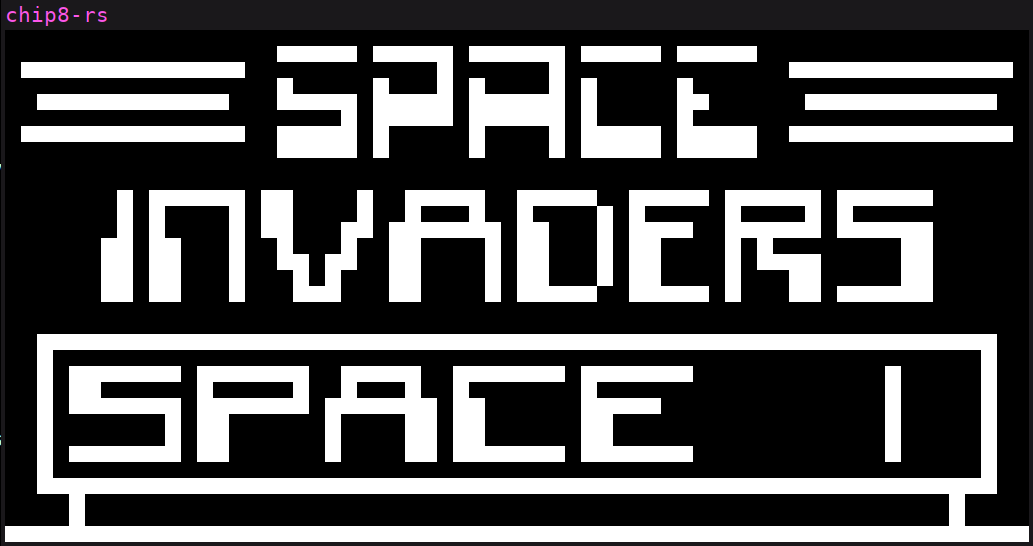
chip8 SDL frontend running the INVADERS game
About SDL video nomenclature
If you’re not familiar with SDL, you may find it hard to follow the part related to displaying the framebuffer, so I’ll explain some SDL concepts here.
- Window: a window is what you expect, a frame managed by the Window Manager of your operating system where you can draw things inside, and it is also associated with input events (keyboard and mouse).
- Canvas: an area that can be drawn and shown on screen. In SDL, the Window contains a canvas.
- Texture: a 2D rectangular image loaded into memory (if we are using accelerated SDL, like in our case, the texture is loaded into GPU memory).
With this in mind, here’s a description of the process of updating the display:
- First a texture is created
- In the main loop:
- Lock the texture to access it’s buffer. Locking is necessary because the texture is being managed by SDL, and it can’t be read or written without coordination.
- Update the texture content. Since the texture format is RGB24 that’s 1 byte for each color of the RGB (with 3 bytes being 24 bits), I need to update 3 bytes in the buffer.
- Then copy the texture to the canvas. Notice that the canvas size can be bigger than the Chip8 screen, whereas the texture is the exact same size as the Chip8 screen. This copying procedure allows the texture to be scaled by hardware into the canvas.
- Present the window canvas.
Conclusion
In this first article I explained briefly what the CHIP-8 is, and I think it’s a very good candidate for your first emulator. Then I showed how I organized the emulator implementation into a backend and frontend, which is a pattern that can be applied to any emulator implementation and comes with the benefit of portability.
The backend implementation contains the core parts of a simple emulator, making it easy to follow.
The frontend shown in this article is implemented in SDL, and the description gives all the details of how to use SDL for an emulator (except for the sound part which I didn’t explain because the CHIP-8 only plays a single tone, which is not very interesting).
I hope you enjoyed this article, and I encourage you to write a CHIP-8 emulator in your favorite language!