This post is the continuation of CHIP-8 emulator in Rust. Part 1, please check it if you haven’t already!
In this second part I will explain how I ported the CHIP-8 emulator I built in Rust to an embedded ARM microcontroller. I will explain the hardware I chose to build this portable CHIP-8 device, the Rust libraries I used and I’ll give an overview of how the code is laid out. I excluded details about hardware diagrams and explicit mention of how the hardware is connected to each pin because I’m sure the astute reader will be able to figure this out from the code itself.
You can find the source code of the emulator in github
Hardware
Microcontroller
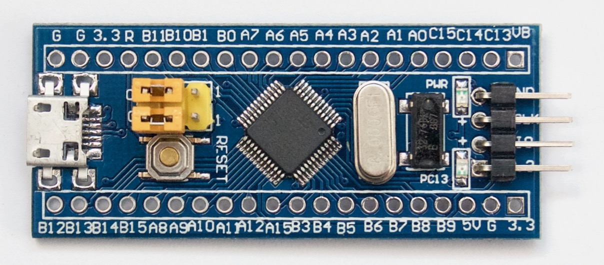
For the microcontroller I’ve chosen the STM32F103C8 via an embedded board commonly called Blue Pill. I’ve used this board in the past with C and Rust with very positive results. Some of the reasons why I like this board a lot are:
- cheap price
- flashing and debugging with open source tools
- ARM 32bit based (much powerful than an AVR based Arduino, and a very well supported architecture in open source toolchains)
- many peripherals
You can find more details about the Blue Pill in the land boards wiki. Nevertheless, here are some technical specs:
- Flash: 64 KB/128 KB
- RAM: 20 KB
- Clock Speed: 72 MHz
Display
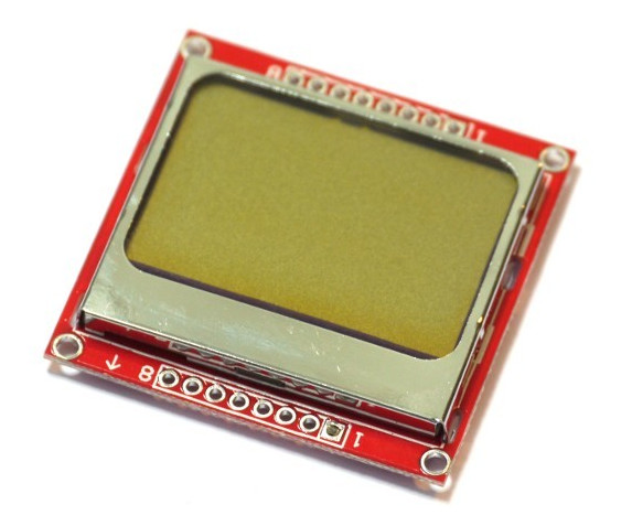
For the video output of the CHIP-8 I have chosen a Nokia 5110 LCD screen which has the following properties:
- pcd8544 driver
- 84x48 pixels
- backlight
The reasoning behind this choice is that there’s an already existing Rust driver implementation for the pcd8544 driver, the CHIP-8 output (64x32 pixels) will fit in the screen (84x48 pixels), and finally there’s the nostalgia factor of having played games on a Nokia 3310 phone when I was young (which has a very similar screen).
Sound
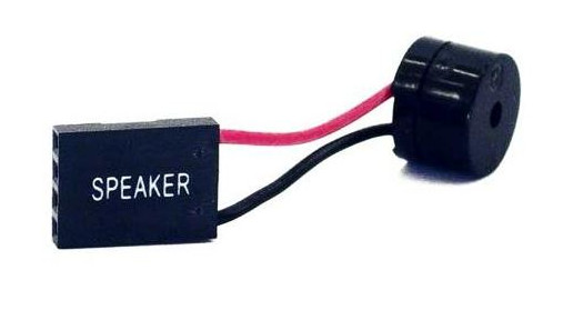
Since the CHIP-8 has a sound (via a single tone output), I added a speaker driven via PWM to control the audio frequency.
Input
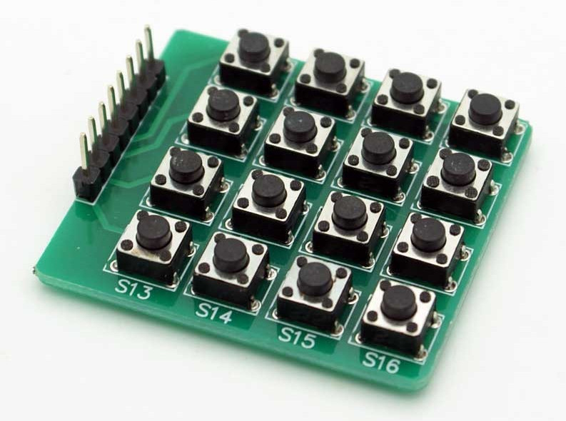
The CHIP-8 is driven by a 16 keys arranged in a 4x4 matrix, and I conveniently found a 4x4 key matrix that will suit this project perfectly.
Summary
I bought the components via AliExpress, but you can find them in other places. I’ve included the price based on what I see now (2021-06-03) in AliExpress for reference.
| Component | Price | Picture |
|---|---|---|
| Blue Pill | 5 EUR |
|
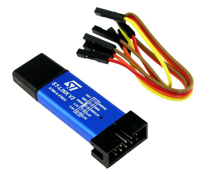
| ST LINK (required to flash the Blue Pill) | 7 EUR |
|
| pcd8544 display | 3.2 EUR |
|
| Speaker | 1 EUR |
|
| 4x4 key matrix | 1 EUR |
|
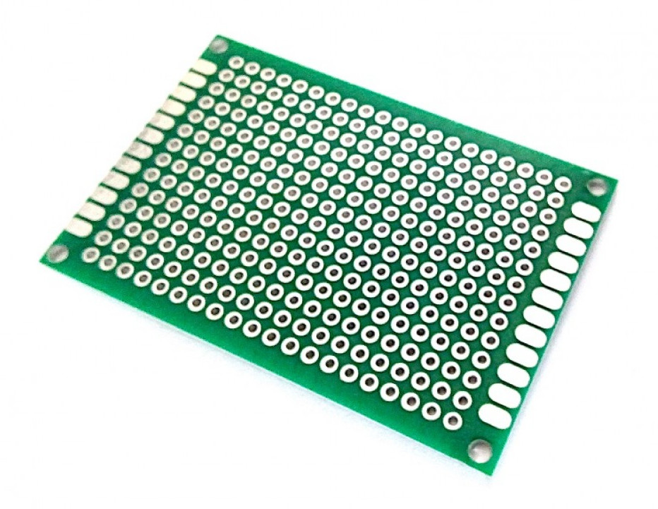
| 4x6 cm PCB soldering board | 3 EUR (10 pcs) |
|
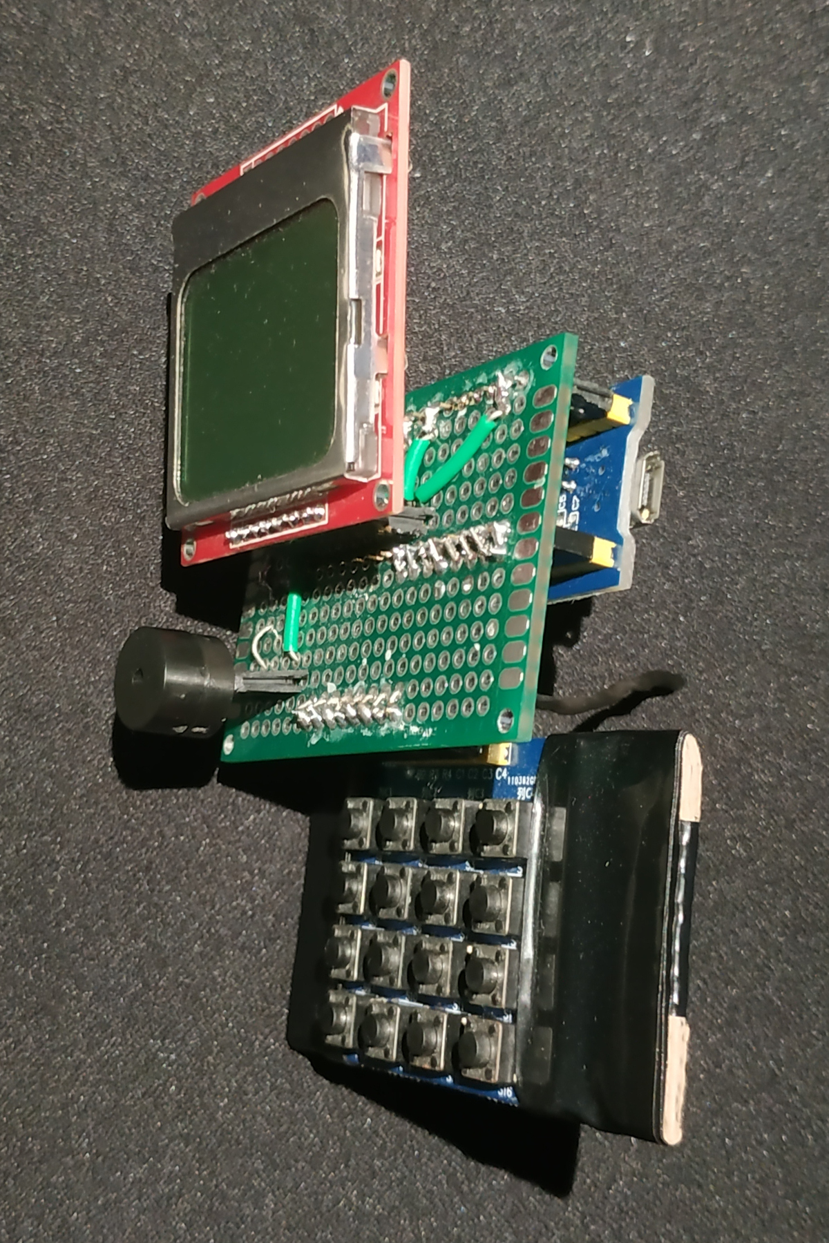
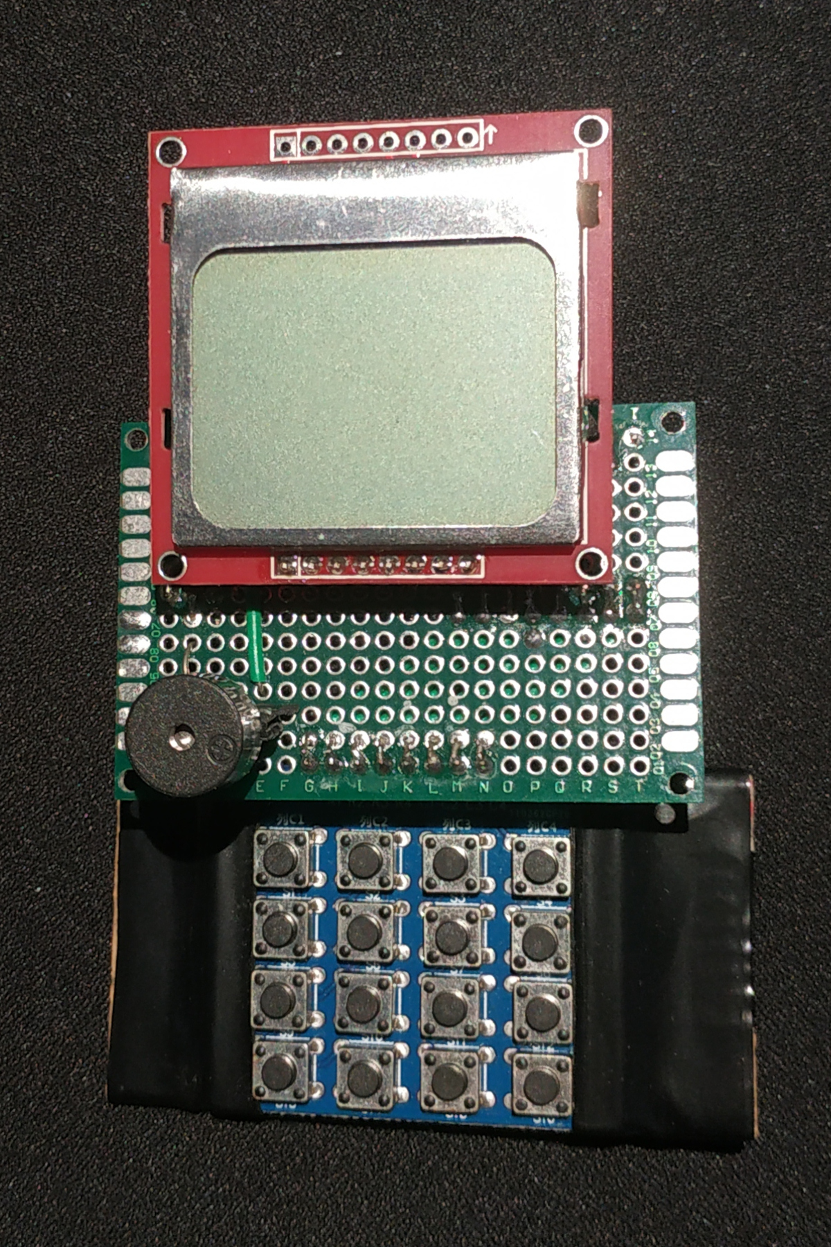
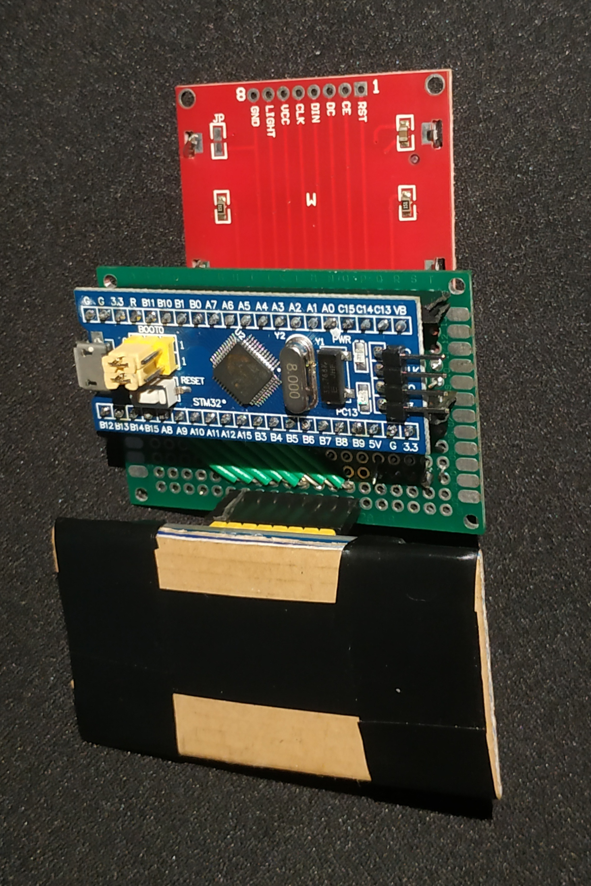
Everything assembled together:
|
|
|
|---|
Software
As I explained in Part 1, I implemented the CHIP-8 emulation
logic as a backend library independent of how the input and output is handled.
In particular, the chip8 library exposes a struct which maintains the state
of the CHIP-8 virtual machine and a method that is supposed to be called 60
times per second called frame, among other methods to query the state of the
frame buffer and tone.
For this embedded port, I introduced a new frontend that will use the chip8
library and handle the inputs and outputs via the hardware shown in the
previous section. To achieve this I extended the workspace with a new project
(the embedded frontend), and now the root Cargo.toml looks like this:
[workspace]

members = [
    "chip8",
    "sdl",
    "stm32",
]
Where stm32 is the new frontend targeting the Blue Pill with the display,
keypad and speaker mentioned in the Hardware section.
External libraries
I have used mainly two hardware libraries:
- stm32f1xx-hal: A HAL
implementation for the STM32F1 microcontroller family based in the
embedded-hal traits. HAL
stands for “Hardware Abstraction Library” and it offers a common API among
different microcontrollers to access the different peripherals (GPIOs,
timers, SPI, etc.). The idea behind the
embedded-halcrate is to define a set of traits for each microcontroller peripheral so that particular libraries (like thestm32f1xx-hal) implement for specific hardware, to make it easy to reuse code when changing targets. - cortex-m and cortex-m-rt: two libraries to access cortex-m functionalities (that’s the family of ARM CPU used in the STM32F1 microcontrollers).
- pcd8544-hal: A PCD8544 (Nokia 5110)
driver, which also uses the
embedded-haltraits.
Software libraries:
- nb: non-blocking IO library for
embedded-haltraits. I’m using this library to block on asynchronous interrupts. - panic-halt: used to set panic
behavior to halt. A rust project requires a definition of panic behavior.
When using
std, the panic behavior is defined as a routine that unwinds the stack to show all the functions that were called until the panic was reached, and then terminate. In the embedded world we don’t have an operating system and thus we losestd, so we need to manually define the panic behavior. - arrayvec: This library provides
Vector-like types that use fixed capacity arrays internally instead of memory from the heap. We require this because we won’t have a memory allocator.
Code overview
Since we don’t have an operating system, we also don’t have access to a file
system API, yet we need some way to access the CHIP-8 ROMs. An easy way to
achieve this is to embed the ROMs contents in the Rust binary with the
include_bytes binary:
static ROM_PONG: &[u8] = include_bytes!("../../games/PONG");
static ROM_INVADERS: &[u8] = include_bytes!("../../games/INVADERS");
// [...]
The following function will query the state of the 4x4 keypad and return a
u16 where a bit is set when the corresponding key is pressed. As you can
see, I wrote this function using the embedded-hal OutputPin and InputPin
traits so that it can be reused with other targets that implement the
embedded-hal traits.
The keypad is arranged as a 4x4 matrix, with 4 horizontal wires (rows) and 4 vertical wires (columns). At each wire crossing a switch button is connected, and when pressed, a short-circuit is created between the crossed wires. In order to figure out the state of the keys, we need to setup the rows as Output pins, and the columns as Input pins. Then we set all rows to Low except for row y; and then we read the value of each column: for each column x that is high, we know that the key at (x, y) was pressed. In this implementation I return as soon as I see a key press, so at most one bit will be set in the result.
fn key_pressed<O: OutputPin, I: InputPin>(r: &mut [O; 4], c: &mut [I; 4]) -> u16 {
    for pin in r.iter_mut() {
        pin.set_low().ok().unwrap();
    }
    for (y, ry) in r.iter_mut().enumerate() {
        ry.set_high().ok().unwrap();
        let is_high = [
            c[0].is_high().ok().unwrap(),
            c[1].is_high().ok().unwrap(),
            c[2].is_high().ok().unwrap(),
            c[3].is_high().ok().unwrap(),
        ];
        for x in (0..4).rev() {
            if is_high[x] {
                return 1 << (y * 4 + x);
            }
        }
        ry.set_low().ok().unwrap();
    }
    0
}
The following code is used to map the values returned by the key_pressed
function to the CHIP-8 keypad layout.
const KEY_0: u16 = 1 << 0xD;
const KEY_1: u16 = 1 << 0x0;
const KEY_2: u16 = 1 << 0x1;
const KEY_3: u16 = 1 << 0x2;
const KEY_4: u16 = 1 << 0x4;
const KEY_5: u16 = 1 << 0x5;
const KEY_6: u16 = 1 << 0x6;
const KEY_7: u16 = 1 << 0x8;
const KEY_8: u16 = 1 << 0x9;
const KEY_9: u16 = 1 << 0xA;
const KEY_A: u16 = 1 << 0xC;
const KEY_B: u16 = 1 << 0xE;
const KEY_C: u16 = 1 << 0x3;
const KEY_D: u16 = 1 << 0x7;
const KEY_E: u16 = 1 << 0xB;
const KEY_F: u16 = 1 << 0xF;

fn key_map(k: u16) -> u16 {
    match k {
        KEY_0 => 1 << 0x0,
        KEY_1 => 1 << 0x1,
        KEY_2 => 1 << 0x2,
        KEY_3 => 1 << 0x3,
        KEY_4 => 1 << 0x4,
        KEY_5 => 1 << 0x5,
        KEY_6 => 1 << 0x6,
        KEY_7 => 1 << 0x7,
        KEY_8 => 1 << 0x8,
        KEY_9 => 1 << 0x9,
        KEY_A => 1 << 0xA,
        KEY_B => 1 << 0xB,
        KEY_C => 1 << 0xC,
        KEY_D => 1 << 0xD,
        KEY_E => 1 << 0xE,
        KEY_F => 1 << 0xF,
        0 => 0,
        _ => unreachable!(),
    }
}
Now we reach the main function. In the first part we need to initialize the hardware and obtain handlers to the peripherals: Embedded Rust libraries treat hardware resources like memory is treated in Rust: you can either have multiple read-only references, or a single read-write reference. For more details about how the different hardware peripherals are initialized, I recommend checking out the examples of the stm32f1xx_hal crate.
#[entry]
fn main() -> ! {
    // Get access to the core peripherals from the cortex-m crate
    let cp = cortex_m::Peripherals::take().unwrap();
    // Get access to the device specific peripherals from the peripheral access crate
    let dp = stm32::Peripherals::take().unwrap();

    // Take ownership over the raw flash and rcc devices and convert them into the corresponding
    // HAL structs
    let mut flash = dp.FLASH.constrain();
    let mut rcc = dp.RCC.constrain();
    let mut afio = dp.AFIO.constrain(&mut rcc.apb2);

    let clocks = rcc
        .cfgr
        .use_hse(8.mhz())
        .sysclk(stm32f1xx_hal::time::Hertz(SYSCLK))
        .pclk1(36.mhz())
        .freeze(&mut flash.acr);

    // Acquire the GPIOC peripheral
    let mut gpioa = dp.GPIOA.split(&mut rcc.apb2);
    let mut gpiob = dp.GPIOB.split(&mut rcc.apb2);
    let mut gpioc = dp.GPIOC.split(&mut rcc.apb2);

    // Configure gpio C pin 13 as a push-pull output. The `crh` register is passed to the function
    // in order to configure the port. For pins 0-7, crl should be passed instead.
    let mut led = gpioc.pc13.into_push_pull_output(&mut gpioc.crh);

    let mut delay = Delay::new(cp.SYST, clocks);

    // setup SPI
    let sck = gpioa.pa5.into_alternate_push_pull(&mut gpioa.crl);
    let miso = gpioa.pa6.into_floating_input(&mut gpioa.crl);
    let mosi = gpioa.pa7.into_alternate_push_pull(&mut gpioa.crl);
    let spi_mode = spi::Mode {
        phase: spi::Phase::CaptureOnFirstTransition,
        polarity: spi::Polarity::IdleLow,
    };
    let spi = Spi::spi1(
        dp.SPI1,
        (sck, miso, mosi),
        &mut afio.mapr,
        spi_mode,
        // 500.khz(),
        4.mhz(),
        clocks,
        &mut rcc.apb2,
    );

    // other pins for PCD8544
    let dc = gpioa.pa4.into_push_pull_output(&mut gpioa.crl);
    let cs = gpioa.pa3.into_push_pull_output(&mut gpioa.crl);
    let mut rst = gpioa.pa1.into_push_pull_output(&mut gpioa.crl);
    let mut pcd8544 = Pcd8544Spi::new(spi, dc, cs, &mut rst, &mut delay);

    // Collect all the GPIOs used for the keypad as rows (output) and columns
    // (input).
    let mut keypad_r = [
        gpioa.pa11.into_push_pull_output(&mut gpioa.crh).downgrade(),
        gpioa.pa10.into_push_pull_output(&mut gpioa.crh).downgrade(),
        gpioa.pa9.into_push_pull_output(&mut gpioa.crh).downgrade(),
        gpioa.pa8.into_push_pull_output(&mut gpioa.crh).downgrade(),
    ];
    let mut keypad_c = [
        gpiob.pb15.into_pull_down_input(&mut gpiob.crh).downgrade(),
        gpiob.pb14.into_pull_down_input(&mut gpiob.crh).downgrade(),
        gpiob.pb13.into_pull_down_input(&mut gpiob.crh).downgrade(),
        gpiob.pb12.into_pull_down_input(&mut gpiob.crh).downgrade(),
    ];

    // Timer TIM2 PWM, used to generate the tone
    let c1 = gpioa.pa0.into_alternate_push_pull(&mut gpioa.crl);
    let mut pwm_tone = Timer::tim2(dp.TIM2, &clocks, &mut rcc.apb1).pwm::<Tim2NoRemap, _, _, _>(
        c1,
        &mut afio.mapr,
        440.hz(),
    );
    let max = pwm_tone.get_max_duty();
    pwm_tone.set_duty(max / 2);

    // Timer TIM3 PWM, used to control the screen backlight
    let c4 = gpiob.pb1.into_alternate_push_pull(&mut gpiob.crl);
    let mut pwm_light = Timer::tim3(dp.TIM3, &clocks, &mut rcc.apb1).pwm::<Tim3NoRemap, _, _, _>(
        c4,
        &mut afio.mapr,
        8.khz(),
    );
    let max_light = pwm_light.get_max_duty();
    const LIGHT_LEVELS: u16 = 4;
    pwm_light.set_duty(max_light / LIGHT_LEVELS * LIGHT_LEVELS);
    pwm_light.enable();

    // Set up a timer that generates an interrupt 60 times per second, which we
    will use to synchronize the frame calculation.
    let syst = delay.free();
    let mut timer = Timer::syst(syst, &clocks).start_count_down(60.hz());

    led.set_high().unwrap();

    // Create an array for all the ROMs that we have included before, with a description string.
    let roms = [
        ("PONG", ROM_PONG),
        ("INVADERS", ROM_INVADERS),
        // [...]
    ];
At this point everything is initialized. Before we run the CHIP-8 emulation,
we need to choose the ROM to load among the list we have embedded into the
binary. In order to do that I implemented a simple text based menu that runs
in a loop at 60 Hz (by using the timer we configured before, blocking until the
interrupt fires). The menu contains a state that is drawn in the screen using
strings, and is updated via key presses. Notice that I use the ArrayString
type in order to build a string dynamically with rust format via the write!
macro.
    // menu loop
    let mut msg = ArrayString::<[u8; 64]>::new();
    let mut light: i16 = 0;
    let mut rom_n: i16 = 0;
    let mut key_prev = 0;
    loop {
        block!(timer.wait()).unwrap();
        let key = key_pressed(&mut keypad_r, &mut keypad_c);
        if key_prev == 0 {
            if key == KEY_C {
                light = core::cmp::min(LIGHT_LEVELS as i16, light + 1);
            } else if key == KEY_D {
                light = core::cmp::max(0, light - 1);
            } else if key == KEY_8 {
                rom_n = (rom_n + 1) % roms.len() as i16;
            } else if key == KEY_2 {
                rom_n -= rom_n;
                if rom_n < 0 {
                    rom_n = roms.len() as i16 - 1;
                }
            } else if key == KEY_5 {
                break;
            }
        }

        pwm_light.set_duty(max_light / LIGHT_LEVELS * (LIGHT_LEVELS - light as u16));

        pcd8544.clear();
        msg.clear();
        write!(msg, "light: {}", light).unwrap();
        pcd8544.set_position(0, 0);
        pcd8544.print(&msg);
        msg.clear();
        write!(msg, "{:02}: {}", rom_n, roms[rom_n as usize].0).unwrap();
        pcd8544.set_position(0, 2);
        pcd8544.print(&msg);

        led.toggle().unwrap();
        key_prev = key;
    }
We create the Chip8 struct, using a CPU cycles counter as a random seed.
Since the previous menu requires user interaction to conclude, the number of
cycles of the CPU at this point will not be deterministic. Afterwards we load
the selected CHIP-8 ROM.
    let mut chip8 = Chip8::new(DWT::get_cycle_count() as u64);
    chip8.load_rom(roms[rom_n as usize].1).unwrap();
Finally we reach the emulation loop, which has a very similar shape to the SDL frontend seen in the previous article. We run the loop 60 times per second (synchronizing it with the hardware timer like we did in the menu). For each iteration, we query key presses, emulate a frame of the CHIP-8, play a tone by enabling the PWM output connected to the speaker if necessary, and update the display with the just calculated frame buffer.
    // chip8 loop

    const DISP_WIDTH: usize = 84;
    const DISP_HEIGHT: usize = 48;
    let mut disp_fb = [0; DISP_WIDTH * DISP_HEIGHT / 8];
    // let mut overtime: usize = 0;
    loop {
        block!(timer.wait()).unwrap();
        let key = key_map(key_pressed(&mut keypad_r, &mut keypad_c));
        chip8.frame(key).unwrap();
        if chip8.tone() {
            pwm_tone.enable();
        } else {
            pwm_tone.disable();
        }
        for b in disp_fb.iter_mut() {
            *b = 0x00;
        }
        for y in 0..chip8::SCREEN_HEIGTH {
            for x in 0..chip8::SCREEN_WIDTH / 8 {
                let byte = chip8.fb()[y * chip8::SCREEN_WIDTH / 8 + x];
                for i in 0..8 {
                    let b = (byte & (1 << i)) >> i << (y % 8);
                    disp_fb[(10 + x * 8 + 7 - i) * DISP_HEIGHT / 8 + y / 8] |= b;
                }
            }
        }
        pcd8544.draw_buffer(&disp_fb);
        led.toggle().unwrap();
    }
}
And that’s all! There’s no functionality to go back to the menu via software; but that’s easily solved by pressing the reset button of the Blue Pill.
Flashing
I will skip the details about how to flash the microcontroller because this
information is very well explained in the stm32f1xx-hal
README.
Nevertheless, if you have doubts feel free to contact me!
Result
Photos

CHIP-8 with AIRPLANE ROM
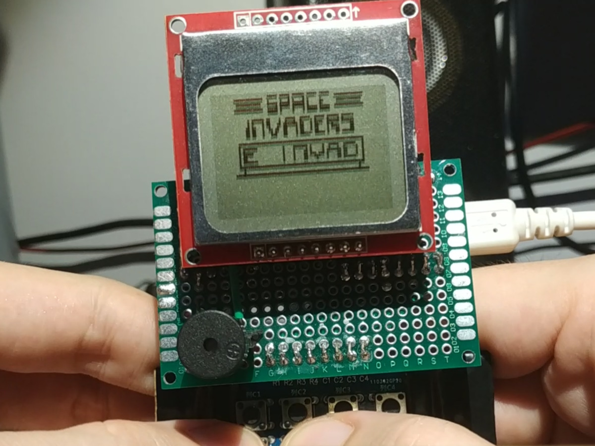
CHIP-8 with INVADERS ROM intro screen
Video
Conclusion
Porting the CHIP-8 emulator I wrote in Rust from SDL to STM32F1 was fairly easy (considering that I was already familiar with building Rust for this embedded platform). The architectural split between frontend and backend was specially useful for this port. This is kind of project is small enough that it can be done in a weekend, and I want to encourage anyone reading this to try doing it because the result of building a small piece of hardware programmed by you that can play games is very satisfying!