In this third and final part of the project about the Game Boy serial communication I will explain how I managed to print on the Game Boy Printer from my PC using an STM32F4 as the bridge between the two. The encoding of the image into Game Boy tiles will happen on the PC, which will send it to the STM32F4 following the packet format of the Game Boy Printer. The STM32F4 will only forward the data to the Game Boy Printer.
Game Boy Printer protocol
You can find all the information about the Game Boy Printer protocol in the second part of this project. That’s all the resources we need to interact with the Game Boy Printer to print images.
Implementation
For this part of the project, the NUCLEO-F411RE will be acting as the master in the Game Boy serial protocol, so we will need to generate the SCK clock signal.
The first step will be to set up the GPIOs, with the only difference that now the SCK will be configured as output.
There’s one particular detail that I missed when I started this part that is essential for the communication with the Game Boy printer to work. The output signals of the Game Boy printer serial port work in open drain mode, that means that the transistor driving the signal will connect the output to ground to signal low, and would leave the output floating to signal high. That means that in order to read high signals properly there needs to be a resistor from the output line to VCC. This can be done either by connecting a physical resistor, or from the NUCLEO-F411RE, by configuring the GPIO input as pull-up (which does the same internally).
static void
gblink_master_gpio_setup(void)
{
	// PA0 -> SCK
	gpio_mode_setup(GPIOP_SCK, GPIO_MODE_OUTPUT, GPIO_PUPD_PULLDOWN, GPION_SCK);
	// PC0 -> SIN
	// NOTE: The gameboy printer signals 0 by connecting to ground and 1 by
	// floating.  This means that a pullup resistor is required to read the
	// 1.  Either connect a pullup resistor to the pin (for example
	// 15KOhm), or set GPIO_PUPD_PULLUP as in the following line.
	gpio_mode_setup(GPIOP_SIN, GPIO_MODE_INPUT, GPIO_PUPD_PULLUP, GPION_SIN);
	// PC1 -> SOUT
	gpio_mode_setup(GPIOP_SOUT, GPIO_MODE_OUTPUT, GPIO_PUPD_PULLDOWN, GPION_SOUT);
	gpio_set_output_options(GPIOP_SOUT, GPIO_OTYPE_PP, GPIO_OSPEED_100MHZ, GPION_SOUT);
	gpio_clear(GPIOP_SOUT, GPION_SOUT);

	gpio_set(GPIOP_SD, GPION_SD);
}
To generate the SCK signal at a stable frequency we will configure the timer to trigger periodically and flip the GPIO value in the timer interrupt function.
Configuring the timer at a specific frequency is not straightforward. The NUCLEO-F411RE has only one clock source at a fixed frequency, and from it all the rest of the clocks are generated using frequency multipliers and dividers. The timer clock takes as a source clock the APB1 clock, and through a prescaler it gets a tick frequency. The timer will increment a counter at every tick, and we can configure it to trigger an interrupt when the counter reaches a certain value. As there are many parameters involved in the configuration, it’s easy to get something wrong and end up not getting our intended frequency. If you have an oscilloscope, I would recommend that you analyze the generated clock signal to verify that the frequency is correct.
For those who don’t have an oscilloscope, here’s a trick I used to verify the frequency: Configure the timer and interrupt to flip a GPIO at an audible frequency, connect an earphone to the GPIO, and use an audio spectrum analyzer app on your smartphone (like this one) to verify the frequency.
The following functions set up the timer to trigger at the desired frequency and allow us to start and stop it.
static void
tim_setup(uint32_t freq)
{
	/* Enable TIM2 clock. */
	rcc_periph_clock_enable(RCC_TIM2);

	/* Enable TIM2 interrupt. */
	nvic_enable_irq(NVIC_TIM2_IRQ);

	/* Reset TIM2 peripheral to defaults. */
	rcc_periph_reset_pulse(RST_TIM2);

	/* Timer global mode:
	 * - No divider
	 * - Alignment edge
	 * - Direction up
	 * (These are actually default values after reset above, so this call
	 * is strictly unnecessary, but demos the api for alternative settings)
	 */
	timer_set_mode(TIM2, TIM_CR1_CKD_CK_INT,
		TIM_CR1_CMS_EDGE, TIM_CR1_DIR_UP);

	/* Set the prescaler to run at 1MHz */
	timer_set_prescaler(TIM2, ((rcc_apb1_frequency * 2) / 1000000) - 1);

	/* Set the initual output compare value for OC1. */
	timer_set_oc_value(TIM2, TIM_OC1, 0);

	/* Disable preload. */
	timer_disable_preload(TIM2);
	timer_continuous_mode(TIM2);

	/* count full range, as we'll update compare value continuously */
	timer_set_period(TIM2, (1000000 / freq) - 1);
}

static inline void
tim_start(void)
{
	/* Counter enable. */
	timer_enable_counter(TIM2);

	/* Enable Channel 1 compare interrupt to recalculate compare values */
	timer_enable_irq(TIM2, TIM_DIER_CC1IE);
}

static inline void
tim_stop(void)
{
	timer_disable_counter(TIM2);
	timer_disable_irq(TIM2, TIM_DIER_CC1IE);
}
As mentioned before, in the timer interrupt we will be flipping the SCK signal, and similar to the second part, on the falling edge we will prepare the output bit, and on the rising edge we will read the input bit. I decided to reuse the printer state machine to keep track of the Game Boy Printer reply (that is, the ACK and STATUS byte), and those two bytes will be the only ones I’ll send over USART (the rest are just ‘0x00’, so there’s no need to send them). The data to be sent will be stored in the ‘recv_buf’ buffer, and once the buffer is empty we will stop the timer.
void
tim2_isr(void)
{
	if (timer_get_flag(TIM2, TIM_SR_CC1IF)) {
		if (high) { // FALLING
			(gb_sout & 0x80) ? gpio_set(GPIOP_SOUT, GPION_SOUT) : gpio_clear(GPIOP_SOUT, GPION_SOUT);
			if (gb_bit == 0) {
				switch (master_mode) {
				case PRINTER_MASTER:
					printer_state_update(gb_sout);
				}
			}

			gpio_clear(GPIOP_SCK, GPION_SCK);
		} else { // RISING

			gb_sin |= gpio_get(GPIOP_SIN, GPION_SIN) ? 1 : 0;
			gb_bit++;

			if (gb_bit == 8) {
				switch (master_mode) {
				case PRINTER_MASTER:
					switch (printer_state_prev) {
					case ACK:
						usart_send_blocking(USART2, gb_sin);
						break;
					case STATUS:
						usart_send_blocking(USART2, gb_sin);
						break;
					default:
						break;
					}
					break;
				}

				// Reset state
				gb_bit = 0;
				gb_sin = 0;

				// Prepare next gb_sout
				if (buf_empty(&recv_buf)) {
					gb_sout = 0x00;
					stop = 1;
				} else {
					gb_sout = buf_pop(&recv_buf);
				}
			} else {
				gb_sout <<= 1;
				gb_sin <<= 1;
			}

			if (stop) {
				tim_stop();
			}

			gpio_set(GPIOP_SCK, GPION_SCK);
		}
		high = !high;

		/* Clear compare interrupt flag. */
		timer_clear_flag(TIM2, TIM_SR_CC1IF);
	}
}
The following function acts as the main loop; it will receive data from the PC via USART, store it in the ‘recv_buf’ buffer and start the timer to send the stored data to the Game Boy Printer.
static void
mode_master_printer(void)
{
	uint8_t len_low, len_high;
	uint16_t len;
	unsigned int i;

	gpio_set(GPIOP_SCK, GPION_SCK);
	high = 1;

	// Block until we get confirmation that the printer has ben turned on
	usart_recv_blocking(USART2);

	while (1) {
		len_low = usart_recv_blocking(USART2);
		len_high = usart_recv_blocking(USART2);
		len = len_low | ((uint16_t) len_high) << 8;

		buf_clear(&recv_buf);
		for (i = 0; i < len; i++) {
			buf_push(&recv_buf, usart_recv_blocking(USART2));
		}

		gb_bit = 0;
		gb_sin = 0;
		stop = 0;

		// Prepare fist byte
		gb_sout = buf_pop(&recv_buf);

		tim_start();
	}
}
Now, the only remaining part is the PC side, where we need to take an image, encode it as Game Boy tiles, and prepare the packets using the Game Boy Printer format. Considering the fact that we can choose the picture margins that the printer will add, we can print long images by printing several times without margin in between.
We start with a helper function that will create and send a packet to the Game Boy Printer, taking care of sending the lengths and the proper checksum:
fn send_print_cmd<T: SerialPort>(
    port: &mut BufStream<T>,
    cmd: PrintCommand,
    payload: &[u8],
) -> Result<Option<PrinterStatus>, io::Error> {
    // Tell stm32f411 the data length
    port.write_all(&u16_to_low_high(10 + payload.len() as u16))?;
    // write magic
    port.write_all(&PRINT_MAGIC)?;
    // write cmd
    port.write_all(&[cmd as u8])?;
    // write arg
    port.write_all(&[0x00])?;
    // write len
    port.write_all(&u16_to_low_high(payload.len() as u16))?;
    // write payload
    port.write_all(payload)?;
    // write crc
    port.write_all(&gen_crc(cmd, payload))?;
    // write empty array to receive ACK and STATUS
    port.write_all(&[0; 2])?;
    port.flush()?;

    let mut ack_status = vec![0; 2];
    try!(port.read_exact(&mut ack_status));
    if ack_status[0] == PRINT_ACK {
        return Ok(Some(PrinterStatus::from(ack_status[1])));
    } else {
        return Ok(None);
    }
}
Next we will use the following function to print a single image, sending the proper packets to the Game Boy Printer and waiting for it to finish:
fn print<T: SerialPort>(
    port: &mut BufStream<T>,
    tile_rows: &[Vec<u8>],
    margins: (u8, u8),
) -> Result<(), io::Error> {
    // Init printer
    println!("Initializing printer...");
    let status = check_ack!(send_print_cmd(port, PrintCommand::Init, &[])?);
    if status.any_info() {
        return Err(Error::new(ErrorKind::Other, format!("{:?}", status)));
    }
    // Send data
    println!("Sending data to printer...");
    for tile_row in tile_rows {
        check_status_error!(check_ack!(send_print_cmd(port, PrintCommand::Data, &tile_row)?));
        check_status_error!(check_ack!(send_print_cmd(port, PrintCommand::Status, &[])?));
    }
    // Send 0 length data to notify the Printer that we've sent all data
    check_status_error!(check_ack!(send_print_cmd(port, PrintCommand::Data, &[])?));
    // Print
    println!("Printing...");
    check_status_error!(check_ack!(send_print_cmd(port, PrintCommand::Print,
                                                  &[0x01, margins.0 << 4 | margins.1, 0xE4, 0x40])?));
    // Query Printing status
    let sleep_time = Duration::from_millis(500);
    loop {
        thread::sleep(sleep_time);
        let status = check_ack!(send_print_cmd(port, PrintCommand::Status, &[])?);
        check_status_error!(status);
        if !status.any_info() {
            println!("Printing successfull!");
            break;
        } else if !status.printer_busy {
            return Err(Error::new(ErrorKind::Other, format!("{:?}", status)));
        }
    }
    return Ok(());
}
To encode the image we want to print into tiles, we use the following function, which takes an image and returns a vector of tile rows (the exact same data representation that the Game Boy Printer uses). This function will also convert the image color space from 8 to 2 bits by using the thresholds 0-63, 64-127, 128-191, 192-255. I highly recommend converting the image to 2 bit grayscale color space using an external program that supports dithering, like GIMP for better results.
fn img_to_tile_rows(img: image::GrayImage) -> Vec<Vec<u8>> {
    let mut tile_rows: Vec<Vec<u8>> = (0..img.height()/16).map(|_| vec![0u8; 640]).collect();
    for row in 0..img.height()/8 {
        for col in 0..img.width()/8 {
            for y in 0..8 {
                let mut lsb = 0 as u8;
                let mut msb = 0 as u8;
                for x in 0..8 {
                    let p = img.get_pixel(col * 8 + x, row * 8 + y).data[0];
                    let (low, high) = if p < 64 {
                        (1, 1)
                    } else if p < 128 {
                        (0, 1)
                    } else if p < 192 {
                        (1, 0)
                    } else {
                        (0, 0)
                    };
                    lsb = lsb | (low  << (7-x));
                    msb = msb | (high << (7-x));
                }
                tile_rows[(row/2) as usize][((row % 2) * 320 + col*16 + y*2    ) as usize] = lsb;
                tile_rows[(row/2) as usize][((row % 2) * 320 + col*16 + y*2 + 1) as usize] = msb;
            }
        }
    }
    return tile_rows;
}
Finally, the main function starts by taking an input image and transforming it into tile rows, which are then grouped into groups of 9 (which represent the biggest image that the Game Boy Printer can print at once) and sends them to the Game Boy Printer to be printed consecutively, leaving no margin in between:
fn mode_print<T: SerialPort>(port: &mut BufStream<T>, filename: &str) -> Result<(), io::Error> {
    let img = match image::open(&Path::new(filename)) {
        Ok(img) => img,
        Err(err) => {
            println!("Error opening image at file {:?}: {:?}", filename, err);
            return Ok(());
        }
    };
    let img = img.grayscale();

    /* ... */

    let img = img.to_luma();
    let tile_rows = img_to_tile_rows(img);

    // Send confirmation to notify that the printer has ben turned on
    try!(port.write_all(&[0x00]));
    try!(port.flush());

    let k = ((tile_rows.len() as f64)/9.0).ceil() as usize;
    for i in 0..k {
        let margin = if i == 0 {
            (0x00, 0x00)
        } else if i == (k-1) {
            (0x00, 0x03)
        } else {
            (0x00, 0x00)
        };
        let (a, b) = (i*9, cmp::min(i*9 + 9, tile_rows.len()));
        if k != 1 {
            println!("\tPrinting part [{:?}/{:?}]", i+1, k);
        }
        print(port, &tile_rows[a..b], margin)?;
        if i != (k-1) {
            thread::sleep(Duration::from_millis(400));;
        }
    }

    return Ok(());
}
Result
Finally, we can print using the Game Boy Printer. The Game Boy printer uses thermal paper to print: there’s no ink in the printer, the header just heats the paper, which turns dark on the heated spot. Since thermal paper is used in shops and supermarkets to print receipts, I took a receipt, cut it to have 38mm width (the Game Boy Printer paper size), and printed on top of that.
Here are the results!
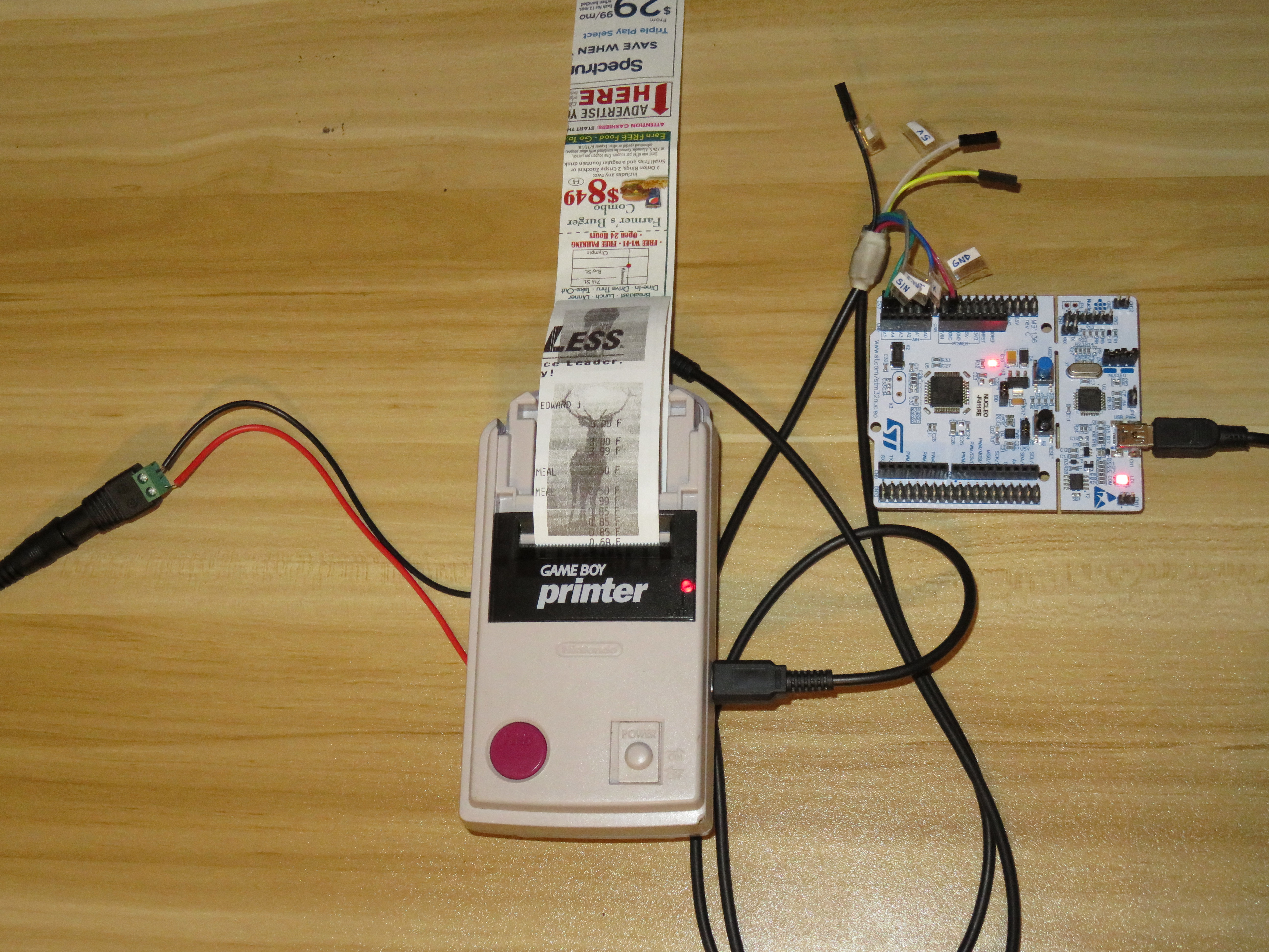
Printing from the PC via the NUCLEO-F411RE
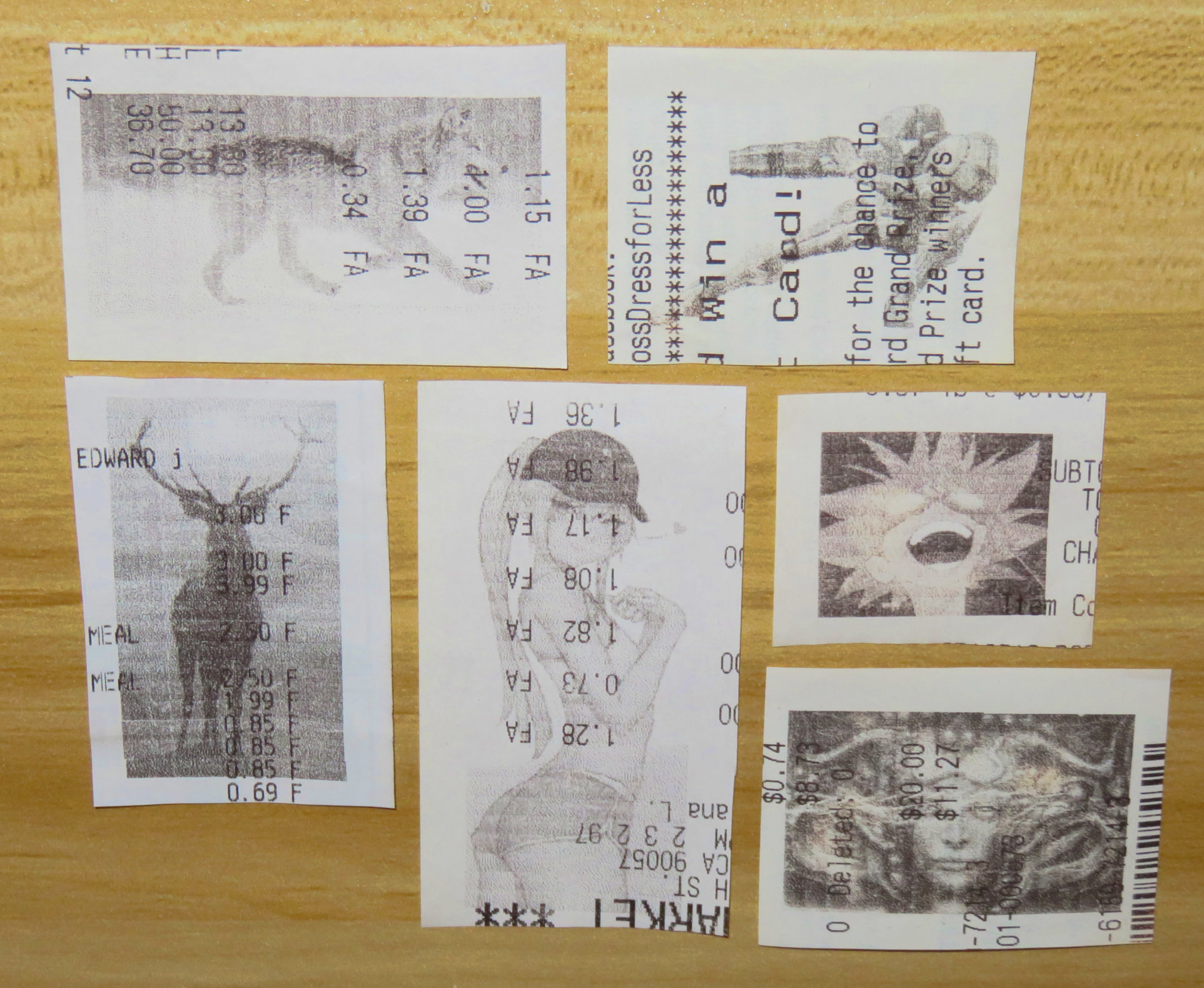
A few pictures printed with the Game Boy Printer on supermarket receipts. This photo is a close up, the pictures are quite small in reality.
To see the full source code of this project, check out the following repositories:
- gb-link-stm32f411: the code that runs on the NUCLEO-F411RE
- gb-link-host: the code that runs on the computer
The source code contains the three parts of the project joined into a single code base.